
The OpenDrop version 1 and 2 used an electrode design that was a best guess on what was reasonable on printed circuit board (PCB). Though the experiments with the first prototypes we gained some more insight and think the shape of the electrodes can be improved. On the current design there is a relatively big gab between the pads due to the process used in PCB manufacturing (min distance of 6 mil or 150 um). And there is almost no overlap with the electrodes despite the zig-zag pattern used. For a next prototype we plan to change to 4 mil (100um) process. Also we did some calculation to compare different shapes. Two processing scripts were developed to quickly design and evaluate electrode shapes.
Current Design
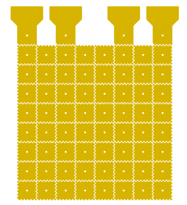
Arrangement and design of electrodes on the OpenDrop V1.
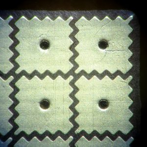
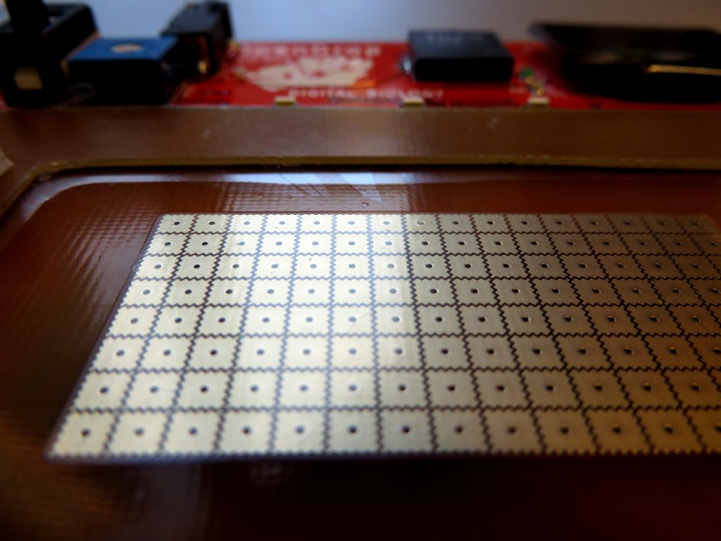
Pictures of the electrodes on the printed circuit board.
Simulations
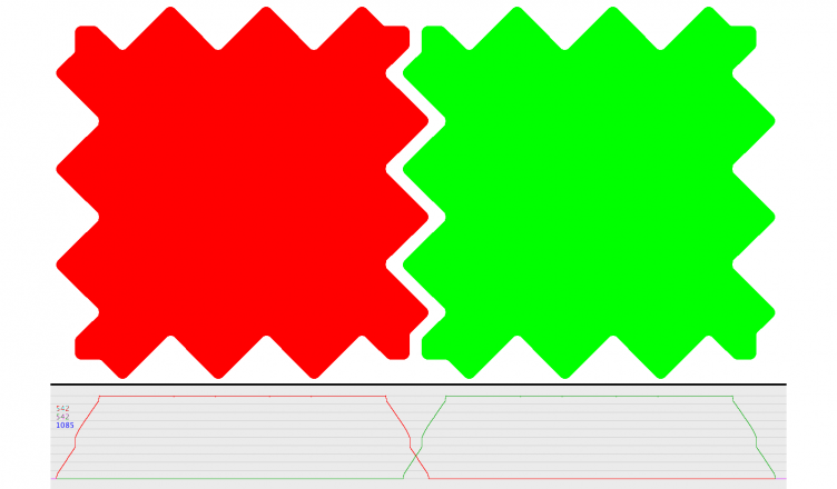
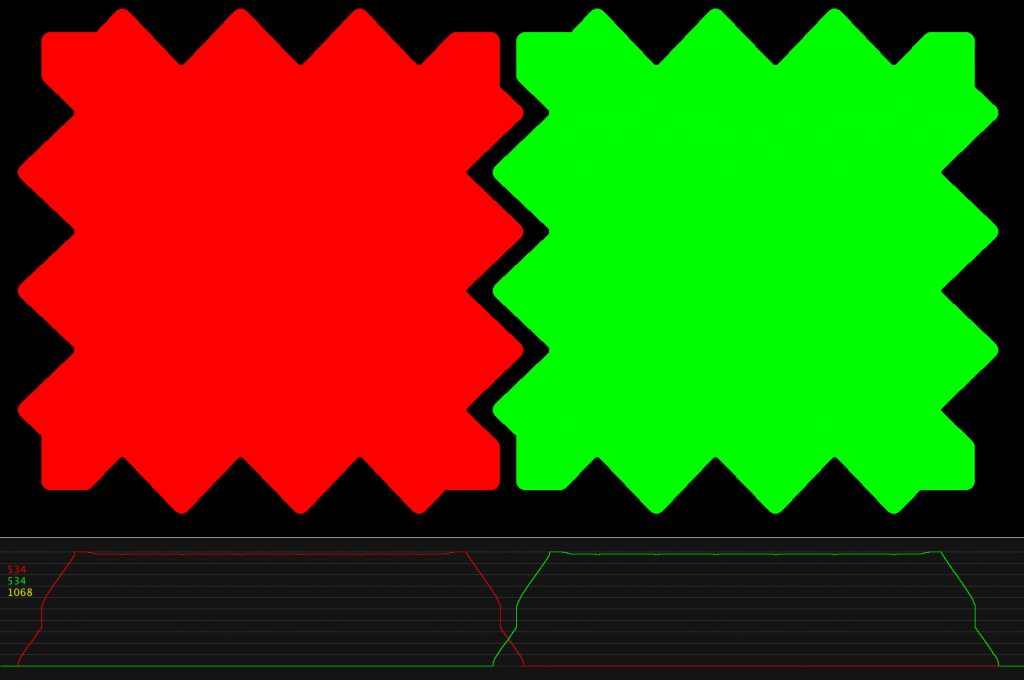
The simulations below show the overlap function of two adjacent pats. The graph represents the total vertical area of the pad in y direction as function of the x direction.
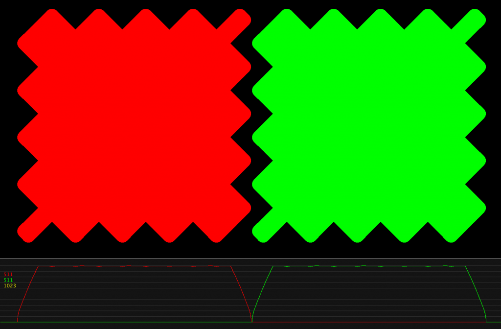
1. In the existing design shows almost no overlap between the two pads.
New designs studied:
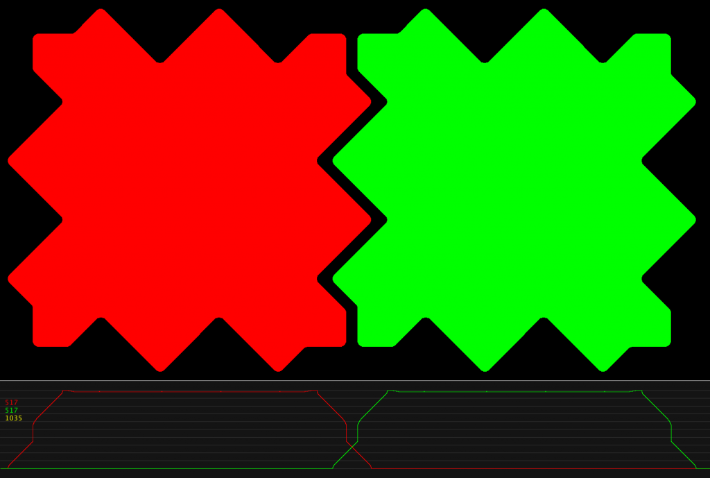
2. Rough zig-zag with two functional teeth.
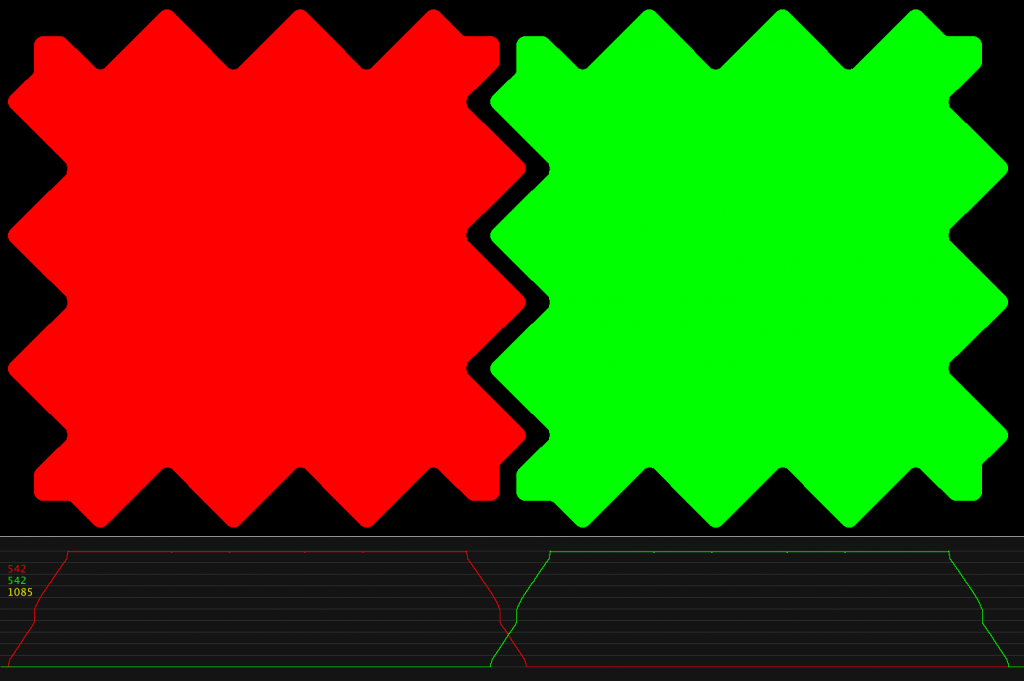
3. Zig-Zag with 2.5 teeth.
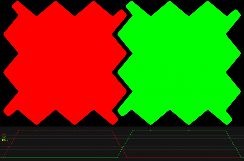
4. Rough zig-zag with two functional teeth, with lower hight.
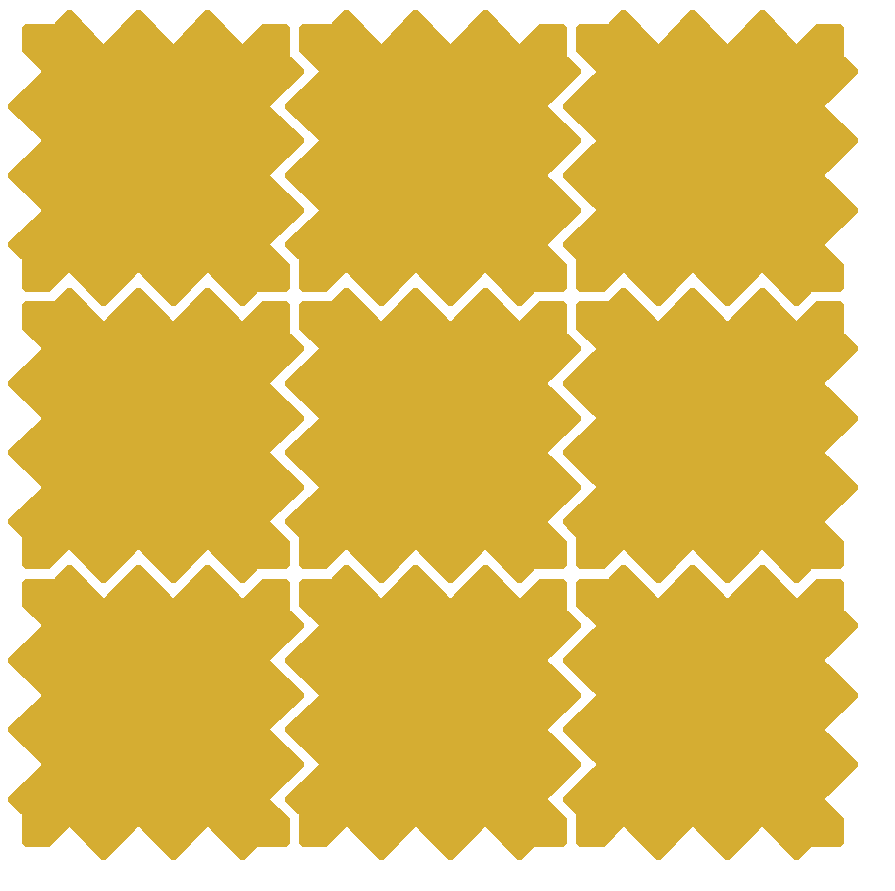
5. Zig-Zag with 2.5 teeth and stronger corners.
Favorite design for the next prototype device (no 5):
Parameters:
process: 4mil
pitch =2 .75/16
overlap = 0.18 mm
padsize = 2.75
 Processsing scripts for
EWOD_Electrode_Design_Processing
Related publications: