
After prototyping and testing of current electrowetting techniques to be used in such a low cost and DIY approach a first devices, OpenDrop V1 was designed to prove the concept. The key elements are the fast fabricating printed circuit board, a scalable electronic control and a simple means of coating.
Speculative design for the experimental research unit.
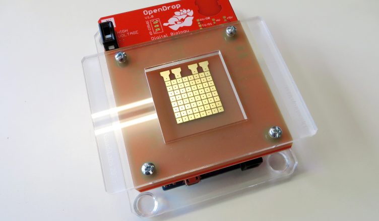
OpenDrop Pictures of Prototype V1
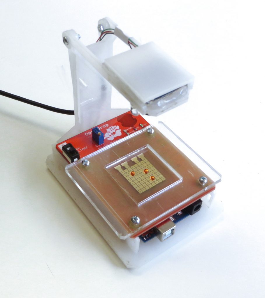
OpenDrop V1 with Camera
Electrode Design
Design on a double layer Printed Circuit Board (PCB) including the electrodes. The board is designed as a shield for the popular Arduino electronic prototyping platform.
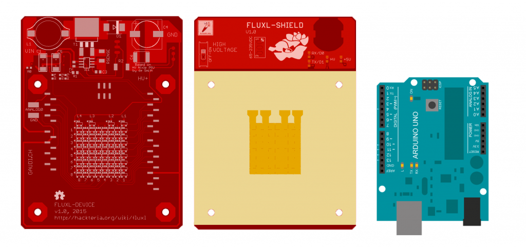
The electrode array is gold coated an contacted to the back with controlling electronics though means of surface mount and through hole Technology
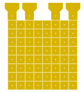
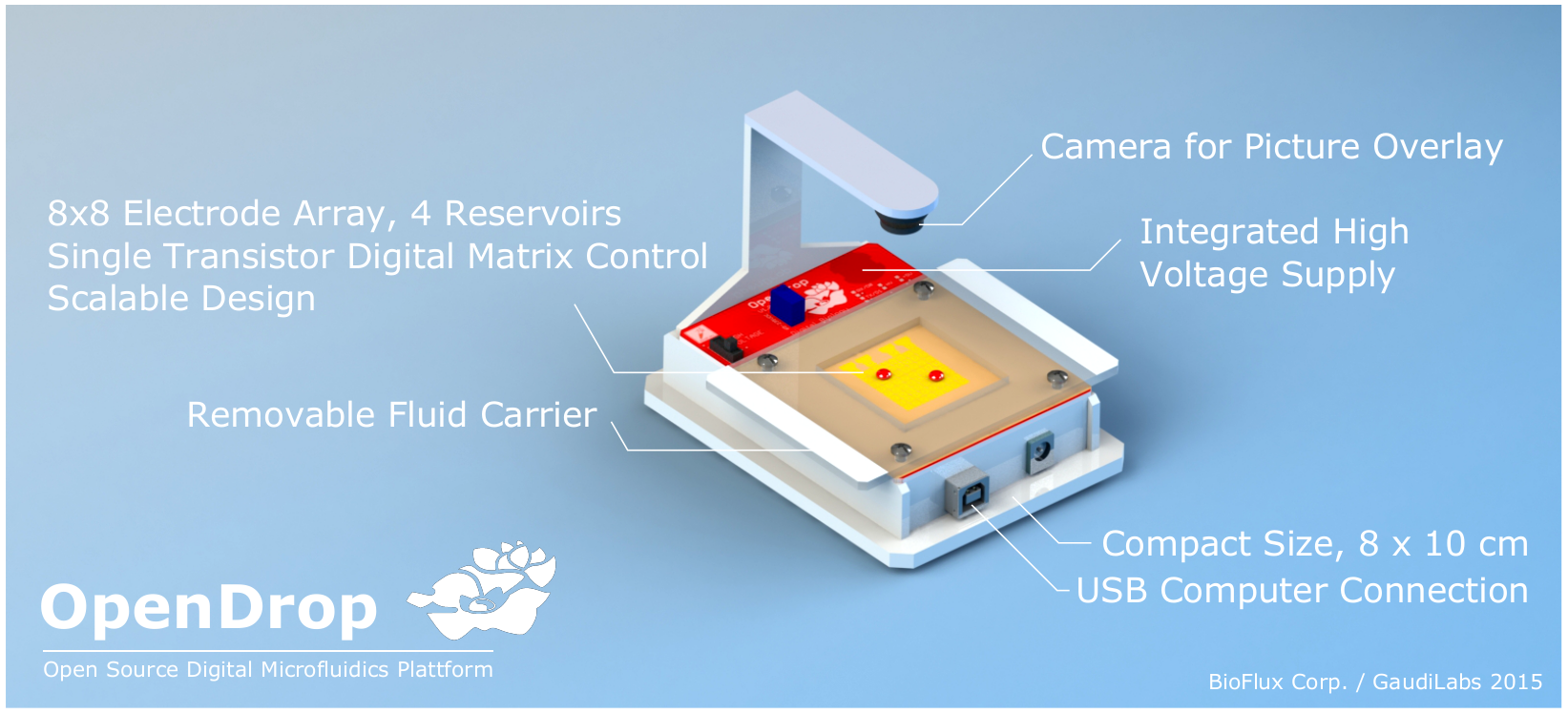
8×8 electrode array with 4 reservoirs.
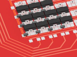
High Voltage Transistors used: BSS131, Infineon SIPMOS, Logic-Level, PG-SOT-23
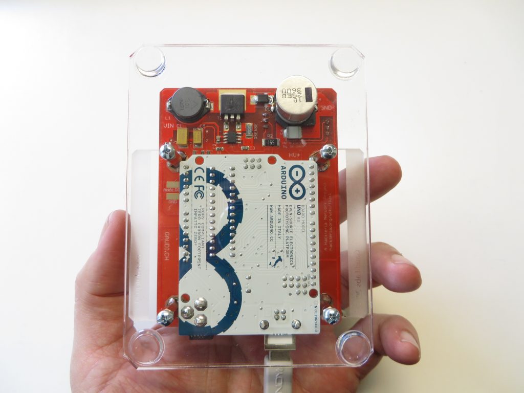
Image of the assembled electronics with the Arduino.
Videos of the working device
Open Drop running MicroDrop Software
Thanks to our great open collaboration with the DropBot team we can now control the OpenDrop through the MicroDrop software. Ryan and Christian Fobel developed a dedicated driver and code for the arduino to support OpenDrop.
OpenDrop running MicroDrop Software
Get the MicroDrop software and drivers for OpenDrop here: http://microfluidics.utoronto.ca/microdrop
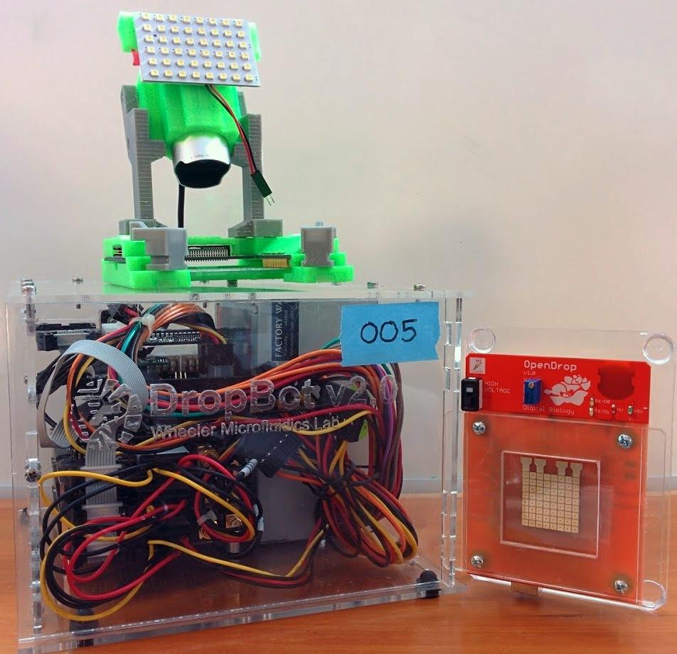
DropBot meet OpenDrop – Open Drop Bots. Image by Ryan Fobel.
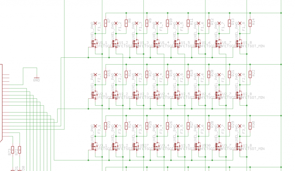
Electronic Circuit
Control of electrodes using a matrix of MosFET transistors on the back of the circuit board.

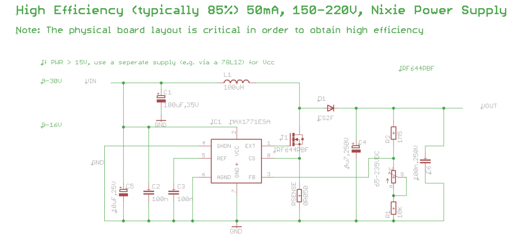
Integrated power supply to generate the high voltage (230V) needed to address the electro-wetting electrodes. Design based on the design “Nixie HV Switching PSU” by Nick de Smith.
http://desmith.net/NMdS/Electronics/NixiePSU.html
http://www.instructables.com/id/NIXIE-TUBE-DRIVER-MODULES-Part-III-HV-POWER-SUPP/

OpenDrop_BOM_(provided by Nathan Saicheck)
Build Instruction for OpenDrop V1
Please consider that the OpeDrop project is still under development and that you need to have good understanding of the circuit and the basic principles to build such a device. Also the electronic boards with SMD components and high-voltage circuits needs advanced skills to prototype. The OpenDrop V1 still has some flaws and needs correction that are described in the following list. We are currently working on OpenDrop V2 that should be more easy to produce and has expanded functionality. If you have questions feel free to ask.
– The array of SMD transistors is quite dense and is best soldered with a reflow soldering process. Also you want to use a stencil to apply the solder paste.
– The source pins of the MosFET transistors are not connected on the current PCB. This would need an extra layer (4 layer design) that we could not afford for this prototype. So you need to solder a wire to all the source pins. (See unrouted wires in eagle board design file)
– The pull-up resistors on the pads need to be 1 MOhm or bigger to avoid excessive heating
– To always insure a defined state of the gate and source pins of the MosFETs additional pulldown resistors can be added (see picture of prototype board)
– For the high-voltage part be sure to also visit the NixiePSU page
We are also still working on a good dielectric film to be applied to the top of the electrodes. Best results so far we got using Saran Wrap coated with Rain-X.
Here some pictures with details on the build.
Images
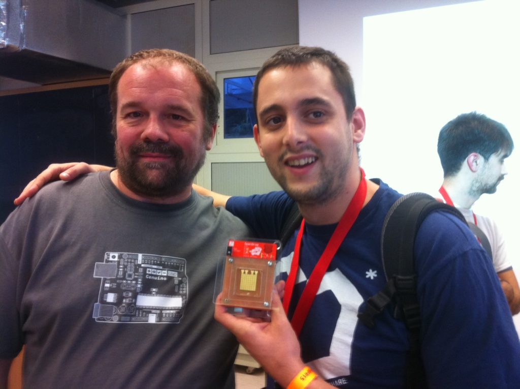
Eugenio Battaglia showing OpenDrop to Massimo Banzi