

Oscillators

Oscillator Schematics
The basic principle of the theremin is the heterodyne oscillator. When I started developing the Open.Theremin I knew that I needed a stable and reliable oscillator. So I searched the internet and found various schematics with different components. I built them each on a small board and connected them to the micro controller to measure the performance. There are huge differences. Some did not work at all for me, others were not stable.
Finally I decided to use a oscillating crystal, that I needed anyway for the micro controller, for the fixed frequency oscillator.
For the variable oscillator I decided for the voltage controlled RC oscillator circuit inside the 4046 phase-locked loop chip. This integrated oscillator revealed to be much more stable than the other circuits I tested. Then there is also a Z-Diode in the package that can be used to stabilize the supply voltage. To adjust the resonated the R1 input can be used. Controlling by VcoIn did not provide better results.
Later on I added the option of an LC oscillator to make the theremin more sensitive (open.theremin.lc).
Resonator Frequencies
I also tested around with the optimum frequency and component values of the oscillators. Clara Rockmores theremin used a coil with 1165uH and 170kHz, the Theremax goes up to 1Mhz while most theremins are in the range of 500-700kHz. I did not find higher frequencies to be significantly better so I decided for 125kHz for the RC circuit and for 500kHz for the LC circuit.
There is an excellent abstract ON THEREMIN SENSITIVITY by Fred Nachbaur
General Notes
- Coupling of the resonators is a problem. It is almost impossible to put two oscillators in one circuit because the two oscillators try to pull one another to a common frequency and extinct the output signal. One IC for each oscillator with proper decoupling condenser is best.
- The hand-to-antenna capacitance is usually only a few picofarads
- The performance of a circuit is hard to predict. Calculations do not always confirm what is common senses among theremin sites. Measurements do not alway confirm calculations...
- With good resonator circuits, decent little theremins with high sensitivity but limited range can be built
- With the microcontroller the response curve can be corrected and even RC theremins can get a wide range (up to a meter distance or so)
- Too low sensitivity and high range is not necessarily more comfortable to play. Playing gets spongy. Truly linear response is not desirable for audio applications since the music note system is exponential and not linear...
- Longer antennas means bigger range
- Center frequency, tank capacity dimensioning and LC or RC did not have a important influence on range and sensitivity in my experiments.
- RC is more suceptible to 50Hz mains hum.
- LC is more stable. I guess due to higher resonace qualit factor.
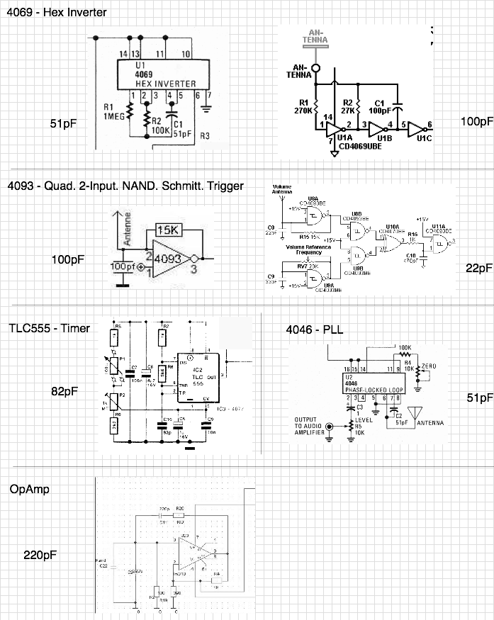
Different Circuits I tested
Here some meassurements of the digitalized and linearized antenna signal:
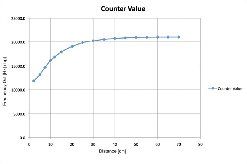
The measured antenna signal (internal counter value)
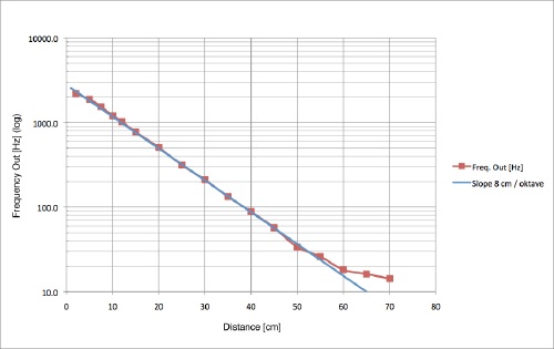
Linearized output signal of the open.theremin
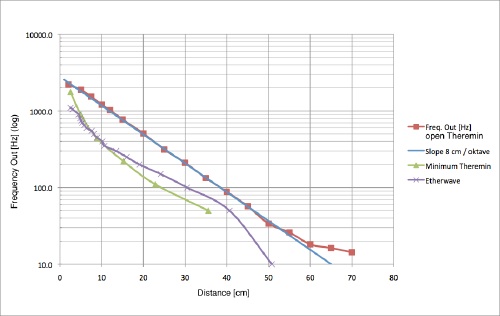
Comparison with two theremin measurements found on the web.