

OpenTheremin V4 Eurorack System

The OpenTheremin is a standalone theremin instrument with built-in oscillators, available as fully assembled, ready-to-play devices. It features control voltage (CV) outputs, allowing seamless integration with existing modular synthesizer systems. This makes it an ideal choice for musicians looking to expand their sound palette and incorporate the unique, touchless playing technique of the theremin into their modular setups.
The following instructions guide you through the process of integrating the OpenTheremin Eurorack modules into your system. These instructions assume that you are familiar with the basics of modular sound systems. If you are looking for a ready-to-play standalone OpenTheremin, we recommend the OpenTheremin V4.5 Electronics and Antenna Kit Bundle or the OpenTheremin V4.5 Deluxe Bundle instead.
OpenTheremin Eurorack Kit

The new Eurorack kit allows the integration of the OpenTheremin into modular Eurorack systems, enabling the creation of a versatile theremin instrument featuring various oscillators, filters, and more.
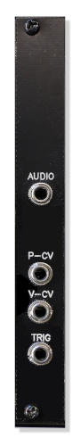
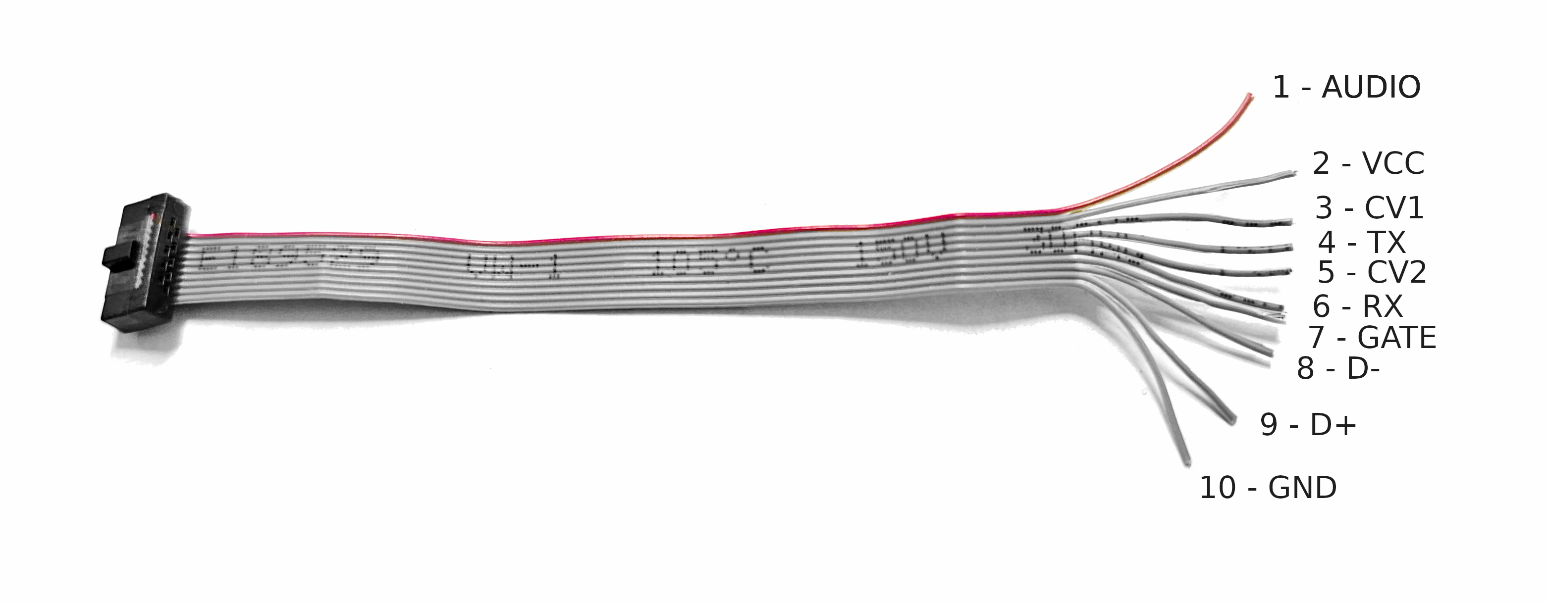
The included breakout module presents all necessary signals, such as control voltage (CV) for both antennas, a gate signal, and the theremin's original mono audio output on the front panel. Additionally, the breakout module includes a full-size DIN MIDI connector, a native USB-C MIDI connector, and a phono output with a separate volume control. This setup allows for extensive connectivity and flexibility in both performance and sound design.
The breakout module connects to the OpenTheremin V4.5 module through an included micro-ribbon cable. The breakout module connects to the rack power supply rail through a standard Eurorack ribbon connector and cable.
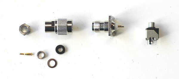
The modular kit comes with a volume and a pitch antenna equipped with solid TNC connectors. A modular system of TNC adapters and two extra antenna front panels provides flexible mounting options to integrate the antennas into the modular system.

Parts included in the OpenTheremin Eurorack Kit

- OpenTheremin V4.5 module with micro-ribbon connector and cable, preprogrammed with MIDI software and GATE signal enabled
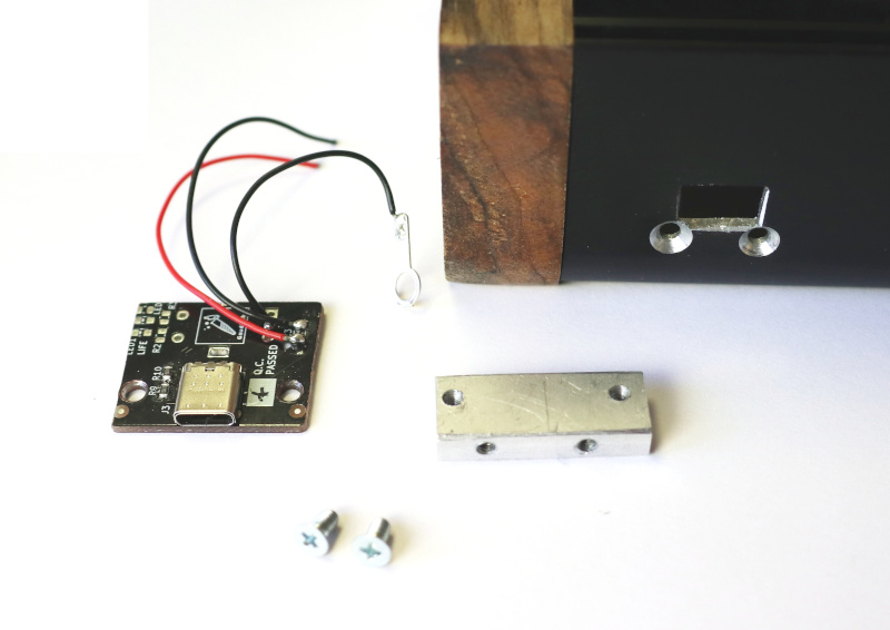
- OpenTheremin Break-Out Module, fully assembled with 3.5mm connectors, full-size MIDI DIN and native USB-C connector, headphone output
- Volume and Pitch Antennas made from 6mm anodized aluminum with TNC connectors
- Antenna Eurorack mounting panels (2x)
- TNC Antenna connectors with connecting wire (2x)
- TNC Antenna angle connectors (2x)
- Eurorack ribbon cable (10-16 pin)
- Mounting screws
The design files and software for all modules are open source and available on GitHub.
OpenTheremin V4 Eurorack kits are available at gaudishop.ch
Build Instructions for the Modular Open Theremin
1. The modular case
The first thing to do is decide on a case to use. You can either build your own case or buy one from a wide selection available. The OpenTheremin works well with an all-wooden case but can also be built into a metal case with just wooden side plates or even in a full metal case. In case of a metal case you will need to be careful with fixing the antenna wires and connectors to prevent them from touching the metal case.
When choosing the case, you also want to consider the size of the case you select. The OpenTheremin can be mounted in cases as narrow as 14 HP and up to 100 HP (508 mm) or more. It all depends on what modules you want to include and how wide your modular theremin should be.
The OpenTheremin is 10 HP wide, the Break-Out module is 4 HP and the antenna mounting panels are 4 HP each.
2. Break-Out Board connections
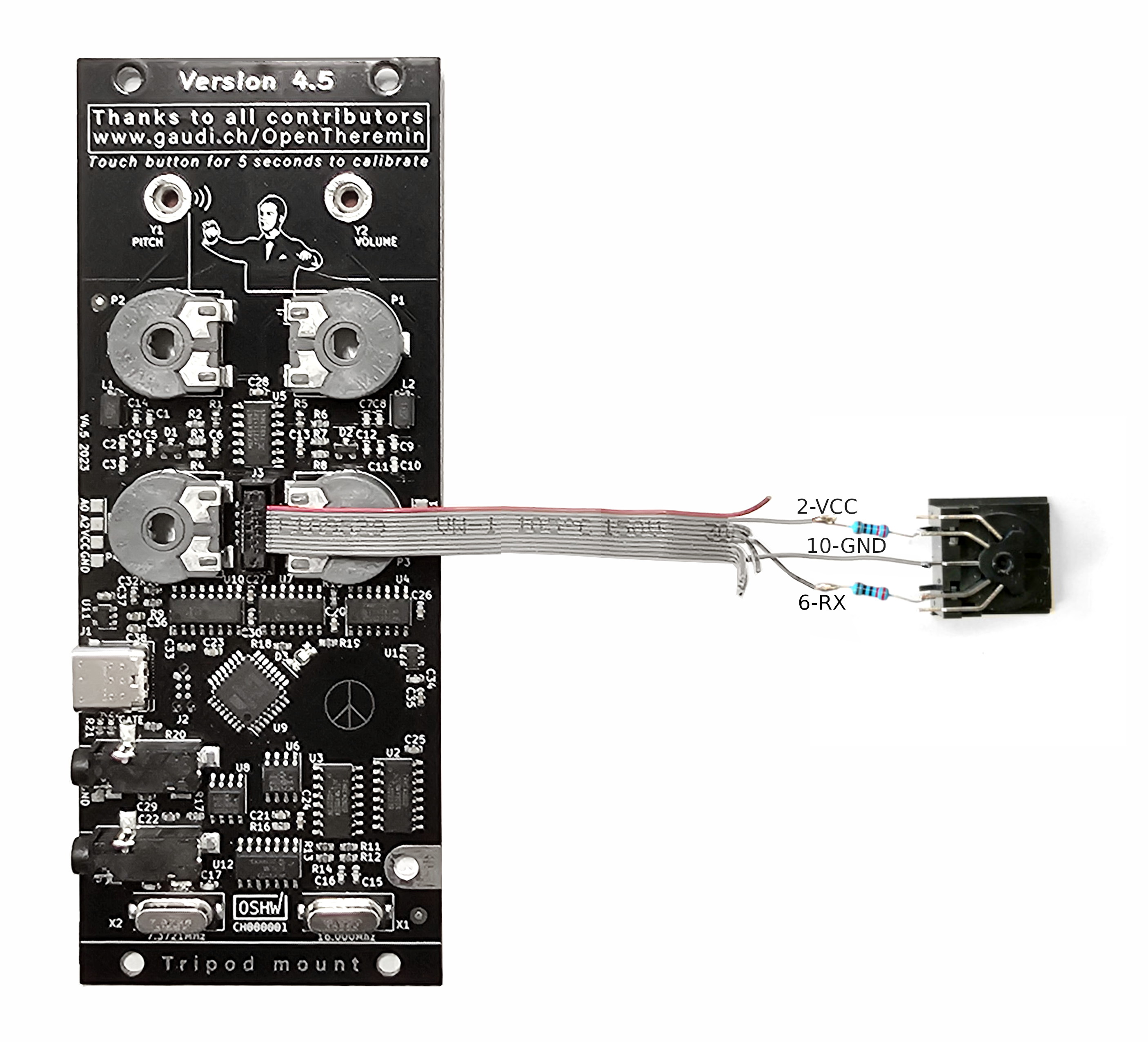
The break-out module allows for easy integration of the OpenTheremin in an Eurorack system. Just connect the micro-ribbon cable of the break-out module to the micro connector on the OpenTheremin and all signals will be wired to the break.out module.

Using the included Eurorack ribbon cable the Theremin modules can be powered through the rack power system. Align the red stripe on the ribbon cable with the "red stripe" marking on both the break-out module and the power bus board of your system, and then securely connect the cable. Alternatively the Modular OpenTheremin can also be powered through the USB-C connection on the breakout module. However this will not provide power to the rest of the system.
3. Antenna connections
The antennas can be connected to the case through the antenna mounting panels.

To mount an antenna with a mounting panel, route the wire of the TNC antenna connector through the hole in the mounting panel and then attach the connector with four M2.5 diameter screws and nuts.
Mount the antenna panels into the Eurorack case.

In an insulating wooden case or with wooden side panels, the antenna connectors can also be directly mounted. With the right woodworking tools, the connector can be slightly recessed, and a cutout can help attach the connectors with screws.

Connect the antenna terminals to the screw terminals of the theremin board using the stiff antenna wire. Cut the wire to length and attach it with plastic wire mounts to prevent the antenna wire from touching the metallic case and to keep it away from any other electrically conductive parts in the system.
Mount the antennas using the 90 degree TNC connector.
Getting started with the Eurorack OpenTheremin with MIDI
Grounding the Theremin
The theremin measures smallest variations between the antennas and your hand and translates this into sound. The electric loop with the instrument is closed from your hand, through the floor into the ground and from ground back into the instrument. This is why proper grounding of the instrument is important. Make sure that your Eurorack system is properly grounded through the power adapter or add an extra grounding wire.
Auto-calibration of the theremin
For the theremin to adapt to it’s environment it needs calibration before playing. The OpenTheremin V4 has an electronic auto calibration built in, it makes calibration very easy. To do so
follow these steps:
a. Power the theremin. Let it warm up for a few minutes.
b. Now turn the two knobs VOLUME and PITCH to the middle position and the knobs REGISTER
and TIMBRE all to the left.
c. Touch the FUNCTION button on the theremin for about 3 second. The LED-light will turn pink and
the theremin will start the automatic calibration of the antennas. To not disturb the calibration step
away form the theremin and wait until the blue LED-light goes back on. The calibration should take
about 60 seconds.
The calibration values are stored in the theremin. So you only have to do this procedure once. If
however you move your theremin or feel that it is not playing well, you can always repeat the
procedure to re-calibrate.
Functionality of the knobs:
The Eurorack OpenTheremin comes with MIDI functionality pre-installed.
The PITCH knob allows you to fine adjust the playing range of the pitch antenna (zero beat).
The VOLUME changes the sensitivity of the volume antenna.
For a good introduction on how to tune the theremin see this introduction by Carolina Eyck:
https://youtu.be/blOmm6e-Qu4
You can mute your theremin by pressing the FUNCTION button.
The REGISTER knob is to select a parameter and the TIMBRE knob to select a value. To change the settings, select a Parameter from the list below and move "Parameter's Value" to change corresponding setting. While you rotate the pots, the LED toggles (OFF/PINK) every steps to give you some angular feedback before going back to PLAY/MUTE Status.
Register: 4 positions as in original Open Theremin V3
Timbre: 8 positions as in original Open Theremin V3
Channel: 16 positions (channel 1 to 16)
Rod antenna mode: 4 positions (Legato off/Pitch Bend off, Legato off/Pitch Bend on, Legato on/Pitch Bend off, Legato on/Pitch Bend on)
Pitch bend range: 5 positions (1, 2, 4, 5, 7, 12, 24, 48 Semitones). For classical glissando and in order to have same note on audio and MIDI, use exactly same pitch bend range on your synth. Maximum setting possible is recomended.
Volume trigger / Velocity sensitivity (how fast moves the volume loop's hand): 128 positions (0 to 127)
Rod antenna MIDI CC: 8 positions (None, 8-Balance, 10-Pan, 16-MSB/48-LSB-GeneralPurpose-1, 17-MSB/49-LSB-GeneralPurpose-2, 18-GeneralPurpose-3, 19-GeneralPurpose-4, 74-cutoff)
Loop antenna MIDI CC: 8 positions (1-Modulation, 7-Volume, 11-Expression, 71-Resonnance, 74-Cutoff, 91-Reverb, 93-Chorus, 95-Phaser)
Default configuration is: Register = Lowest Register, Timbre = 1st Waveform, Channel = MIDI Channel 1, Rod antenna mode = Legato on/Pitch Bend on, Pitch bend range = 2 Semitones, Volume trigger = 0, Rod antenna MIDI CC = None, Loop antenna MIDI CC = 7-Volume.
See also the MIDI page for more information.


 MIDI implementation for OpenTheremin V4 is here! While the Open.Theremin has it's own sound generator and can be played as stand alone instrument the MIDI software allows you to connect your theremin to any MIDI device or various MIDI synthesizers installed on you computer. This largely extend the functionality and is just great fun to play.

