Open.Theremin
|
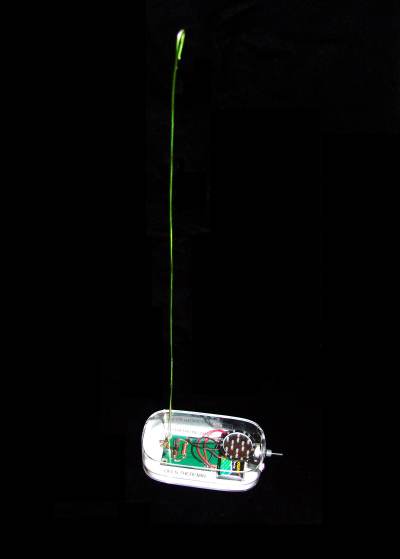
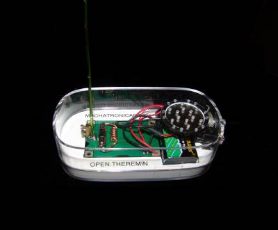
Since Leon Theremin built the first theremin in 1920 many attempts have been made to copy, simplify or improve the original instrument. When I started to develop the open theremin the idea was to build a theremin that was as simple as possible while still playable. And I decided to use the most recent technology. When I looked in the internet I found, that there are simple digital circuits and more complicated analogue ones. Since I wanted some thing simple I tried the digital ones. Basically these are based on the same principle of two resonators (a fixed and a variable one) as the original theremin but use digital signals. Some of the circuits I built simply did not work and some just made some noise. So I tested around quite some time to find the best resonator circuit among all the circuits I found. I decided to use a oscillating crystal to get the most stable fixed frequency oscillator. For the variable oscillator I decided for the voltage controlled RC oscillator circuit inside the 4046 phase-locked loop chip. Later on I added the option of an LC oscillator to make the theremin more sensitive (open.theremin.lc). I also learned that to get a good theremin you really have to be carefully about parasitic effect like mutual influence of the resonators. The circuit is based on SMD technology. This makes the whole theremin really small and at the same time helps to reduce the parasitic effects. Soldering SMD is not difficult if you use reflow soldering. Hand soldering is possible too but I personally think reflow soldering is easier and much more fun. All you need is a pizza oven, solder paste and a way to bring the paste on the circuit. We did the whole process in a SGMK Workshop. Here you can find a nice step by step on DIY reflow soldering. For further information on the open.theremin and the more advanced microcontroller based version open.thremin.up visit the open.theremin Website here. |
|||||
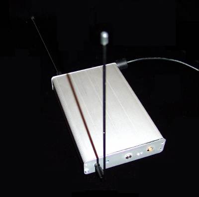
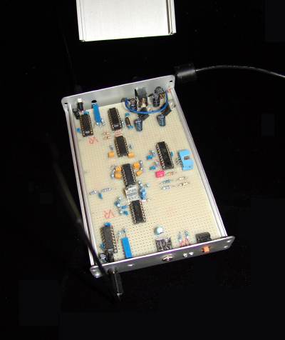
Open.Theremin.UP Prototype
|
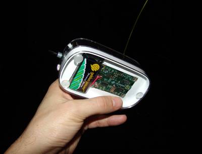
The up.open.theremin is a more complex theremin using a micro controller. The resonator circuits are the same as for the open.theremin. But then the signal is captured by the micro controller. The micro controller can then apply filters, linearize the input signal and synthesize a nice sinusoidal output sound. The up.open.theremin also features a volume control antenna.
|
|||||
Open.Theremin DIY Makeaway
|
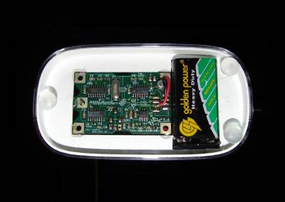
For the public workshops (diy makeaway) I documented the open.theremin on this one sheet flyer. Documented is the PCB layout and where to put the different parts. And the corresponding schematics. For the workshops I put the parts in small containers with the part designator printed on it. You find the part list on the bottom of this page, together with the other files. You can download the page by right-clicking on it. |
|
|
||
 |
DigitalSuper by Urs
Gaudenz is licensed under a Creative Commons Attribution-Noncommercial-Share Alike 3.0 Unported License. | |