Let’s build a spectrometer!
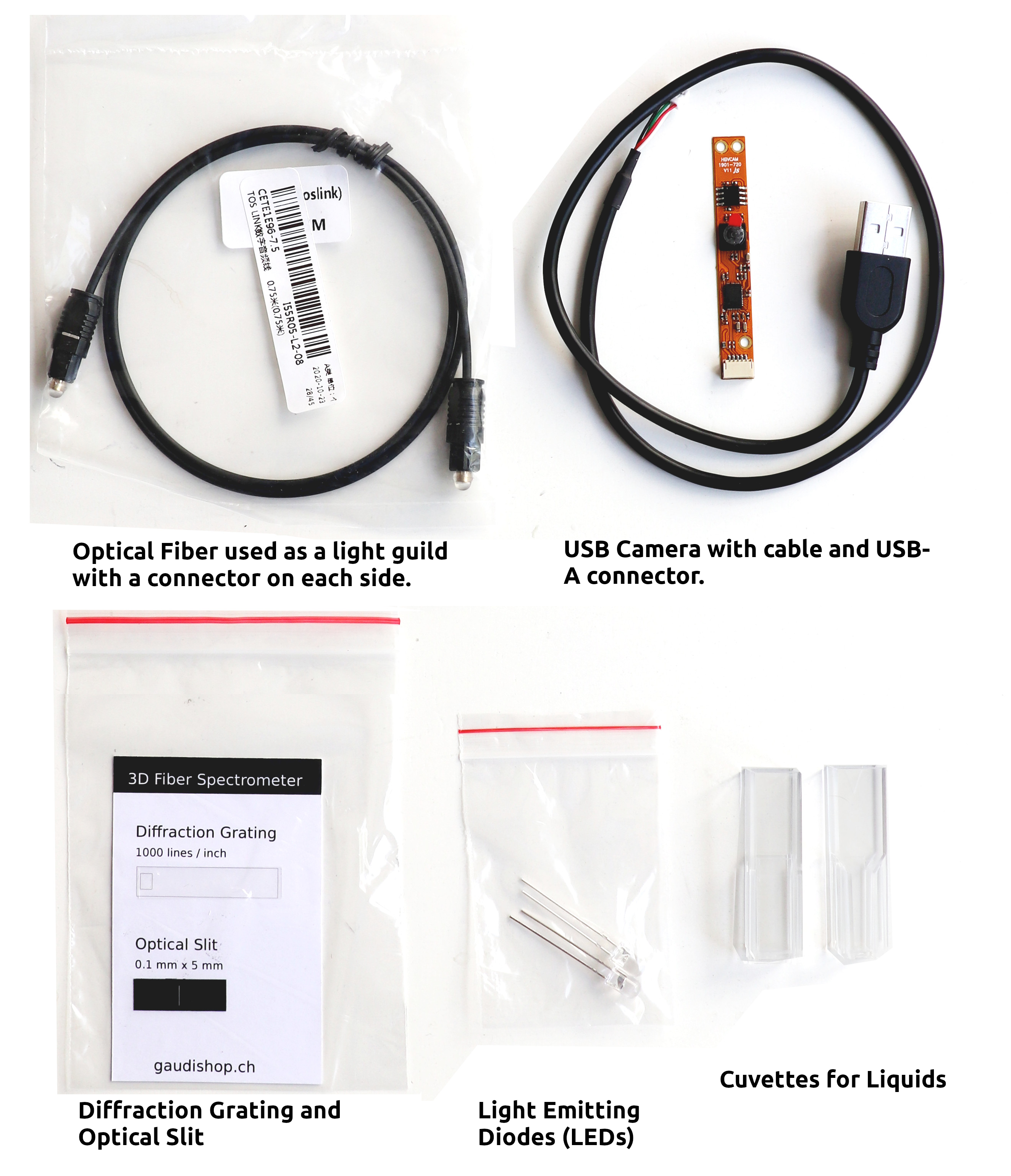
These step by step instructions show you how to build the spectrometer from the “3D Printable Fiber Spectrometer Kit“. First have a look at what is in the kit and if you got all the parts. Do not take the parts out of the bags yet to keep them clean.
The spectrometer is a scientific instrument used to separate and measure components of light. The spectrometer can separate white light and measure individual bands of color, called a spectrum (rainbow pattern). As the spectrometer is an optical instrument we need to precisely guide the light though the optical components and make sure to keep unwanted stray light out. For this let’s first print a solid black case.
Printing the case
The case can be printed on any recent 3D printer using black PLA filament. The case consists of a base that holds the components (File: FiberSpecBaseClip.STL ) and a lid to keep stray light out (File: FiberSpecLid.STL ). Download the parts from the GitHub Repositiory and print them on your printer.
If you do not have access to a 3D printer you can order the 3D printed parts online from imaterialise , shapeways or any 3D printing service. Be sure to order the parts in solid black.
Recommended printer settings are:
- PLA black filament
- 0.4mm nozzle
- 0.16 or 0.2 mm layer height
- 100% infill
- heated bed
- size 100%

If your print bed is big enough you can print both parts at once. Arrange them as shown in the picture.
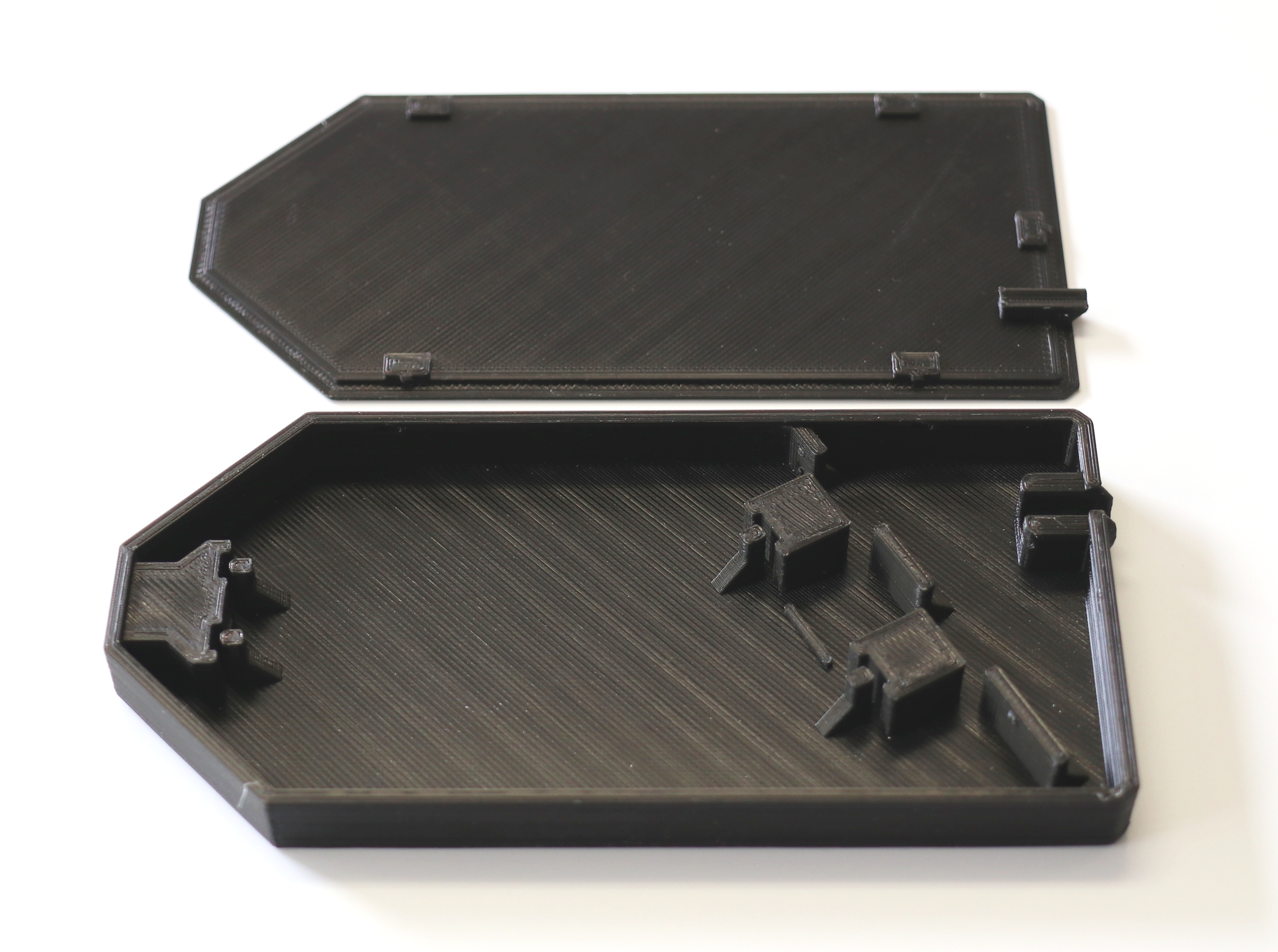
The printed case should look like this. Depending on you print quality you will need to remove some burrs or strings. You can now test to see if the optical fiber connector fits. It may be a bit hard at the beginning and get more loose there after. If the fiber does not fit try tweaking your printer settings by choosing a finer print quality, reducing the layer height or reducing the extrusion rate.
Installing the camera
Now we can start installing the components. Let’s start with the camera.
Remove the camera from the bag and connect the cable using the small white connector. Plug it in carefully as shown on the picture.
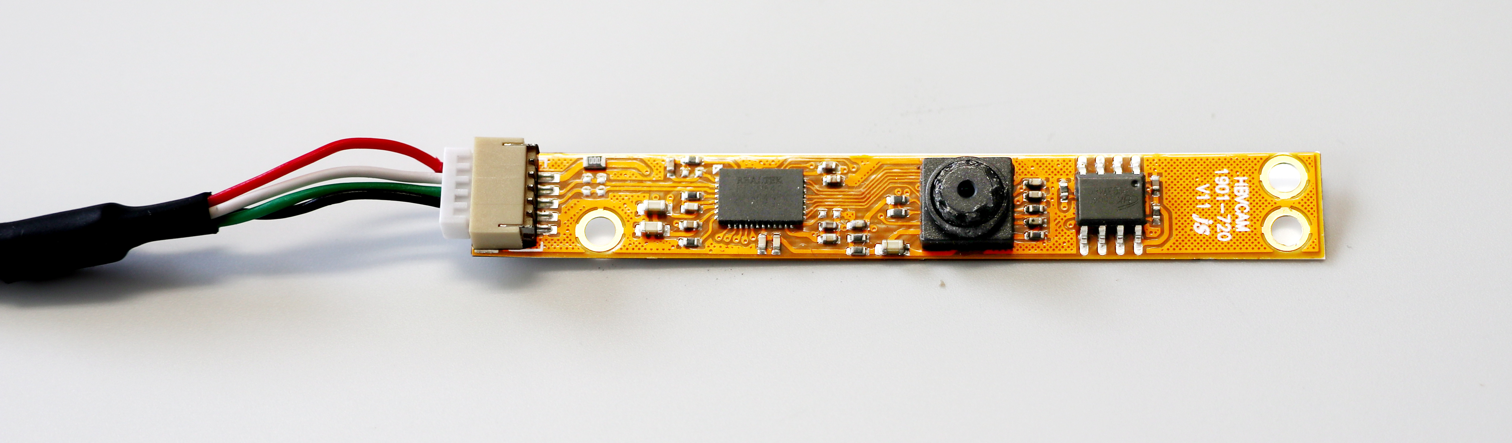
The focus of the small camera is pre-set to the right focal length for the spectrometer. Do not turn the lens unless you want to re-focus the camera.
Next insert the camera into the base part of the case as in the picture. No screwing or gluing is needed. The thin camera circuit board is held between the 3D printed posts. Make sure that the camera is centered and is pressed all the way in to the bottom of the case.
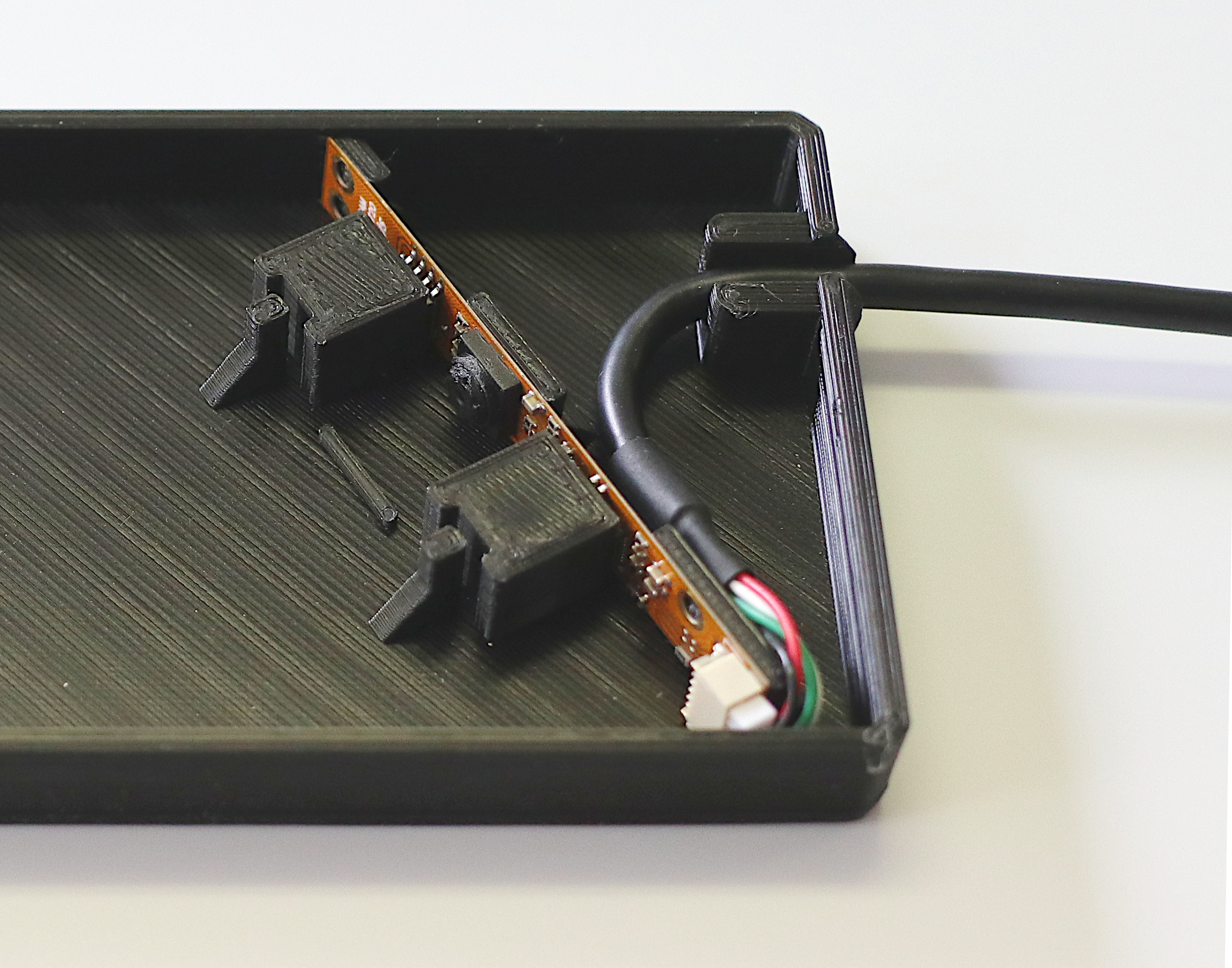
Then bend the cable and press it into the cable fixture.
The Diffraction Grating
The diffraction grating is an optical component that splits and diffracts light into several beams traveling in different directions. Included in the kit is a transparent foil with a microscopic periodic structure that acts like a prism. You can now install it in front of the camera. Take the diffraction grating from the card by holding it on one side. Do not touch the center of the foil as the microscopic structure should remain as clean as possible. Now insert it in the appropriate holder in the case just as you did with the camera. See picture below.
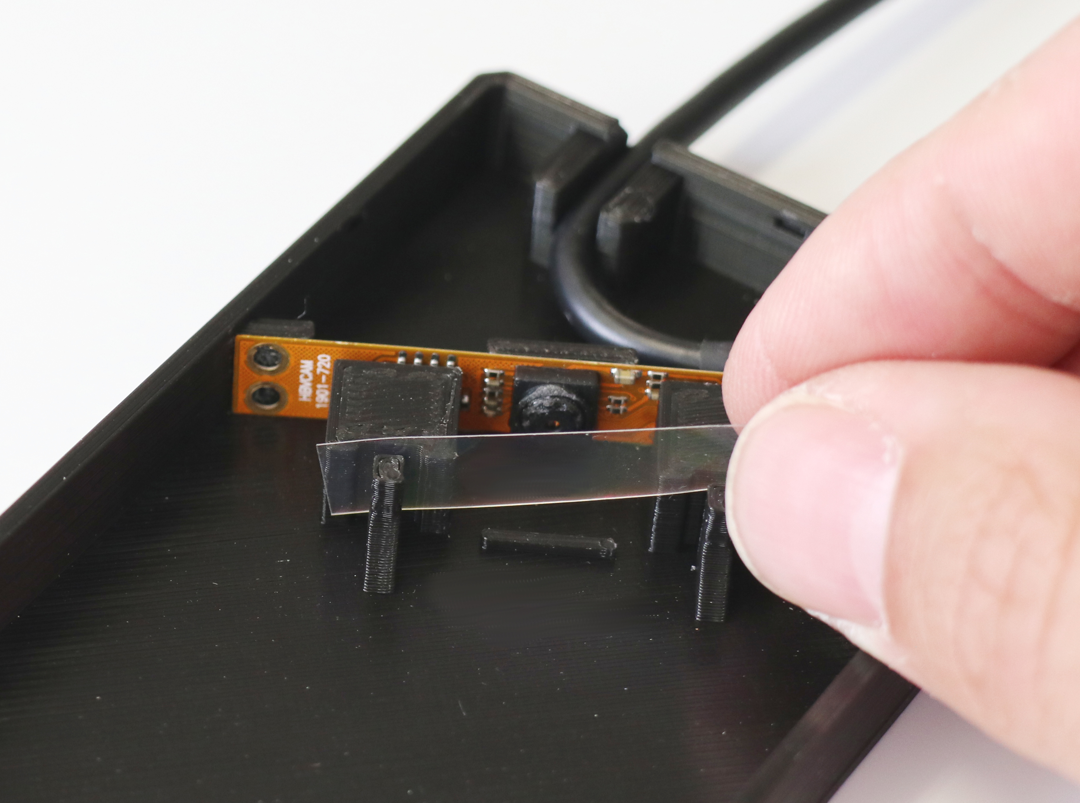
Again make sure the film sits straight, centered and all the way down.
Now you can close the lid for a first test. The lid should fit in snug and hold with the clips. Again no screws needed and you can always re-open the case easily.
First Rainbow Spectrum
 You can now plug in the USB cable to your computer to make a first test. On you computer just use a Web-Cam software to see the image. On Windows 10 use the per-installed “Camera” software. On Mac you can use the “Photo Booth app”. On Linux “guvcview” is a good and free software. With the app started you might need to switch the camera (to USB2.0 UVC HD Webcam) to see the spectrometer. At first you might just see a black screen. Now point the spectrometer towards a lamp or to the sun and you should see the rainbow spectrum.
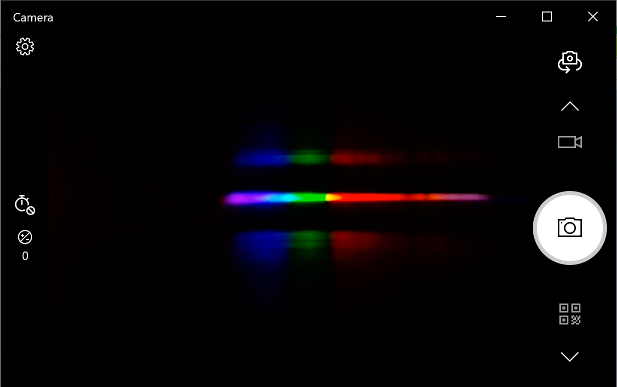
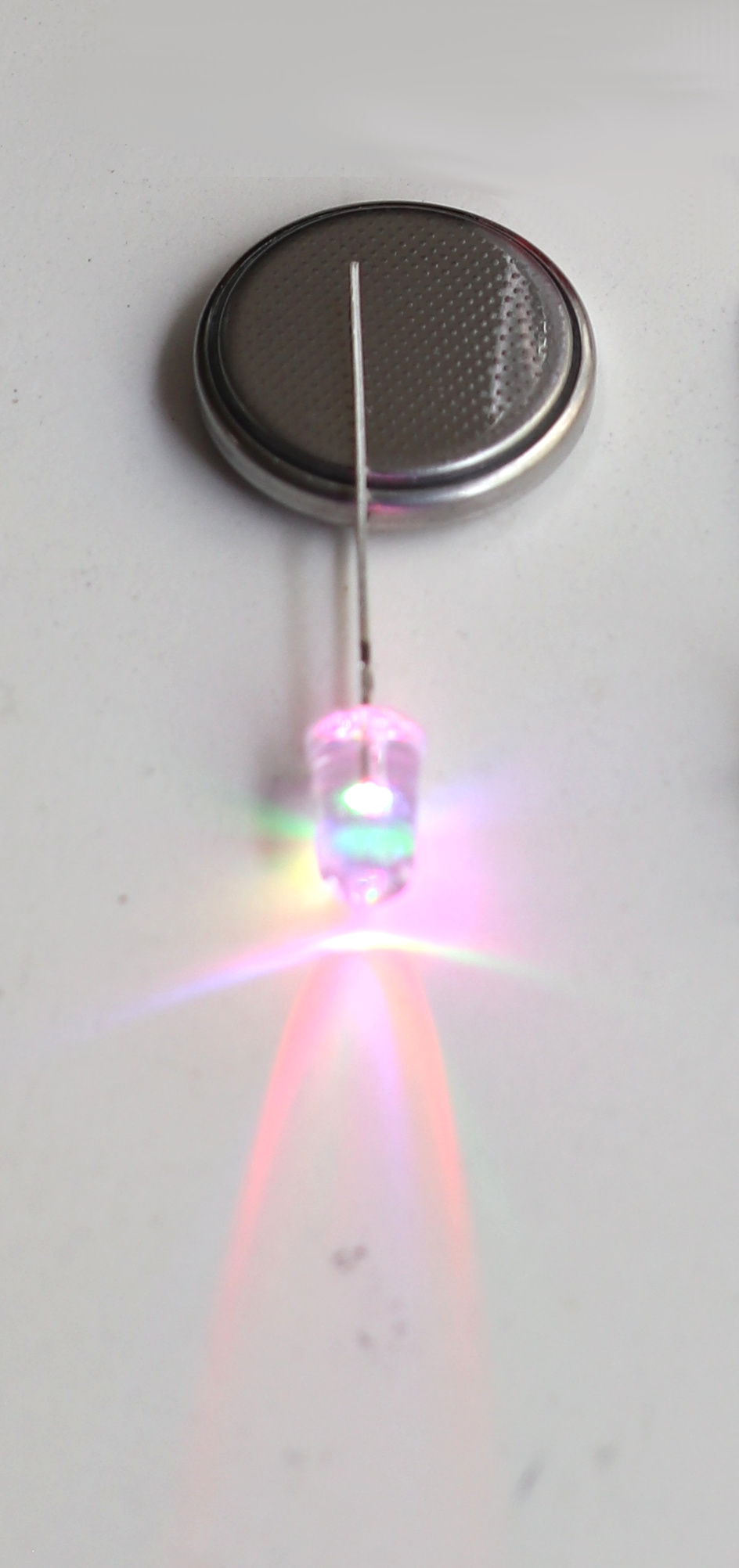
The rainbow spectrum shows the different wavelength components of the light. White light shows the full spectrum. If you point the spectrometer towards a colored light you should only see the wavelength contained in that light source.
The kit contains a white and a color changing light emitting diode (LED). You can point it to the spectrometer to see the different spectras. Pinch a 3V coin battery (not included) between the two legs. The longer leg goes to the plus side.
Your spectrum may look blurry. To improve the resolution you want to reduce the optical aperture of the spectrometer. To do this you can install the optical fiber. It has a smaller opening and focuses the light beam more. The fiber will also allow you to point more precisely to the source you want to measure.
To get an even better spectral resolution you can now install the optical slit.
Optical Slit
Good spectrometers narrow down the incoming light with an optical slit. The slit with a precisely defined width in a black mask is installed at the light entrance port of the spectrometer. The slit included in the kit is printed with of 0.1mm on a foil. Install it as you did with the diffraction grating in the case. See picture below on how to.
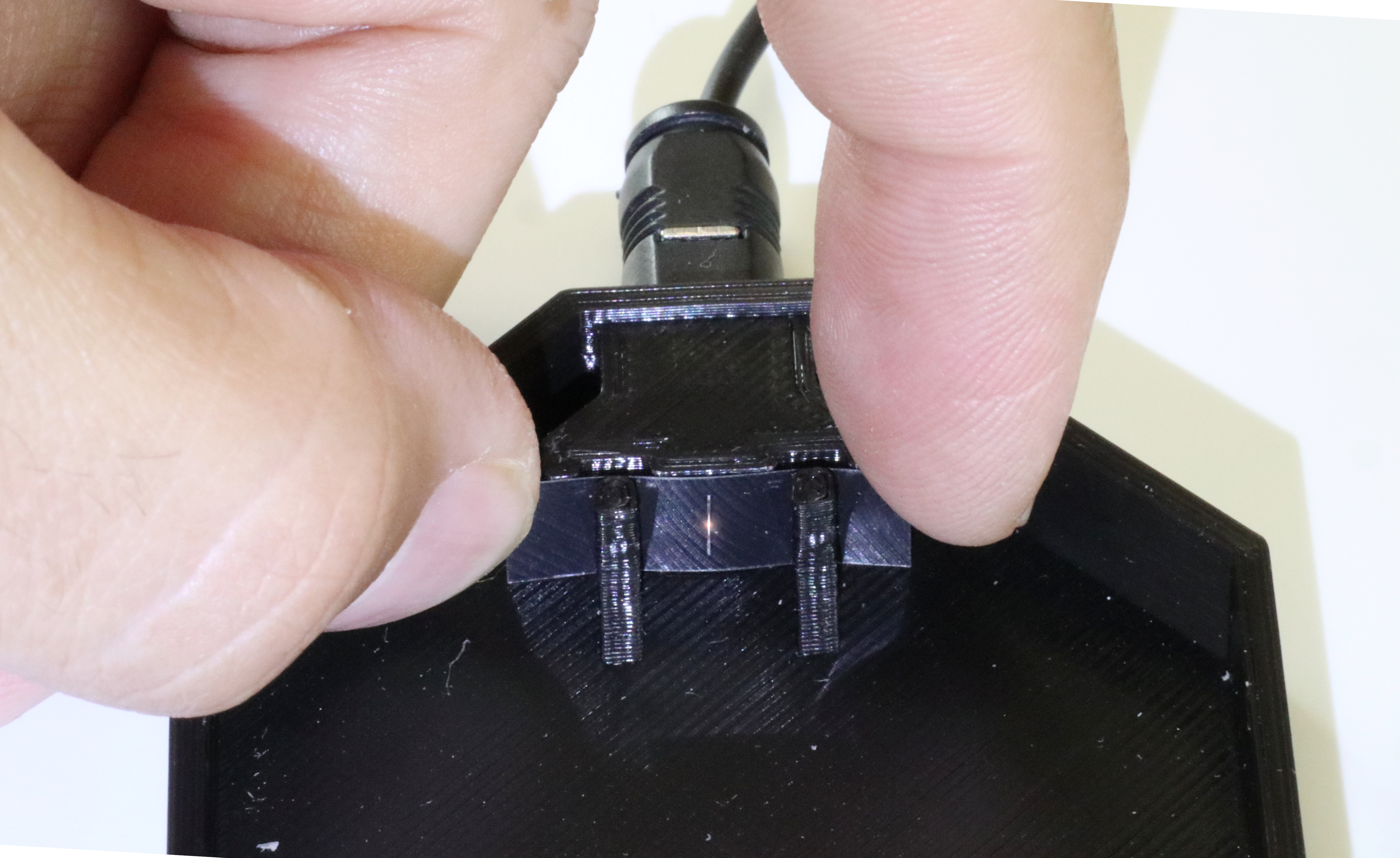
Position the slit in front of the optical fiber and align to get the maximum light through the slit.
Capturing calibrated spectras.
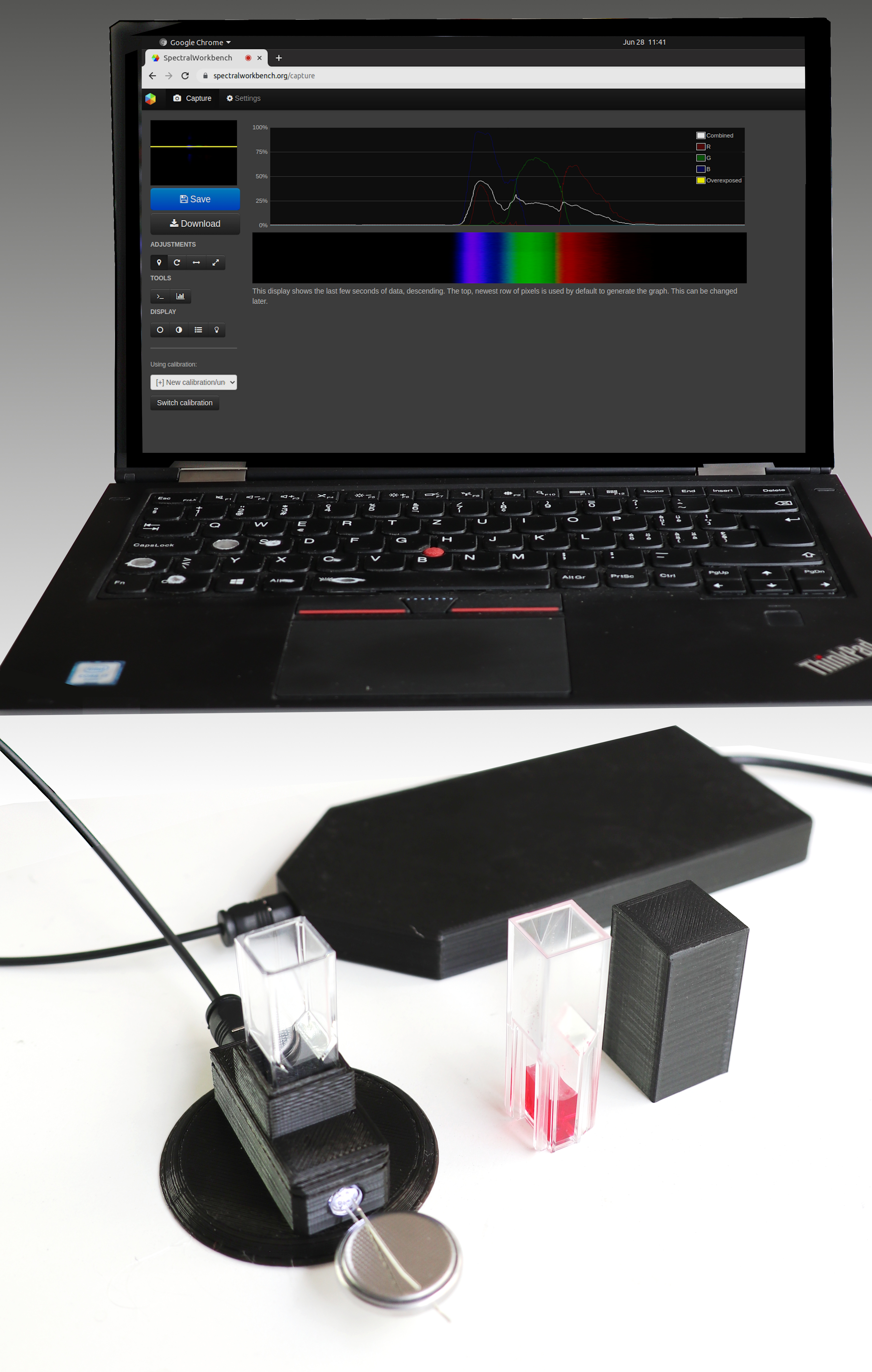
To get calibrated spectral information with a nanometer units scale on the horizontal axis you can use SpectralWorkbench.org . SpectralWorkbench is a web-based software created by Public Lab.
Once you have an assembled spectrometer connected to your computer or smartphone, create an account at https://spectralworkbench.org, log in and click Capture. You’ll then be able to connect to your spectrometer, capture and save spectra, and analyze and share them.
Spectral Workbench is open source software, created by Public Lab
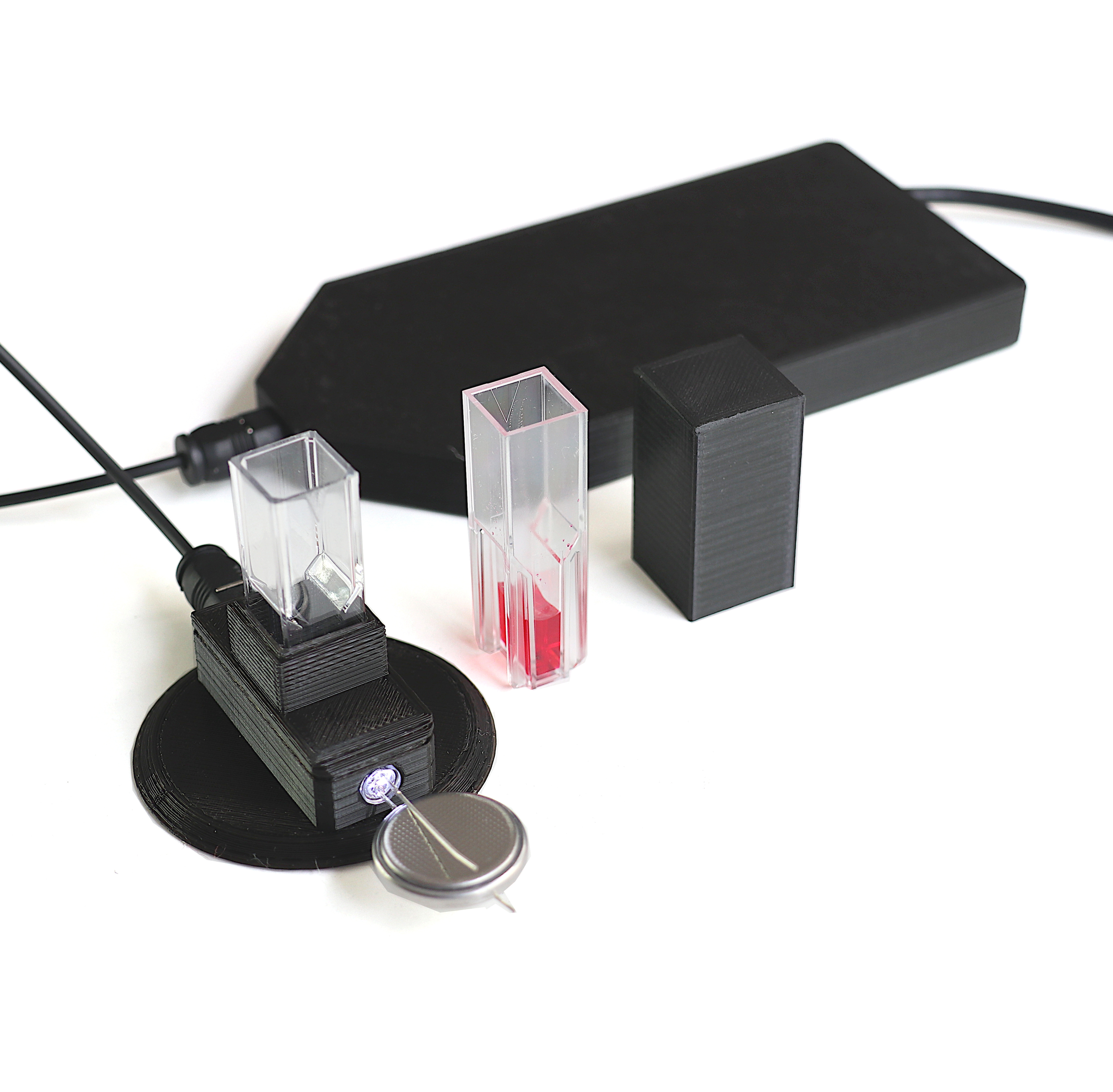
Measuring absorption with the cuvette holder
The big advantage of the optical fiber spectrometer is that you can easily connect the fiber to various different light sources and sample holder. A cuvette holder is a commonly used add on for absorption measurement in liquids. Let’s 3D print one.
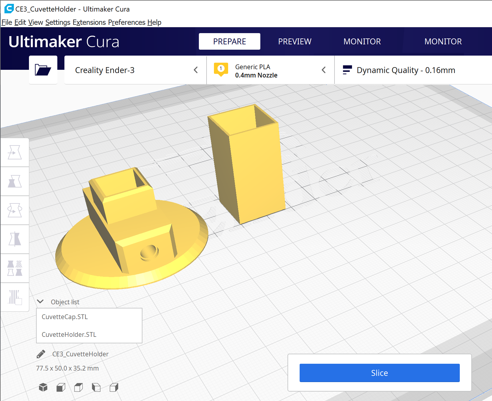
Print the holder CuvetteHolder.STL and the CuvetteCap.STL with black PLA as you did for the case.
One printed you can connect the optical fiber to the cuvette holder and insert the white LED with the coin battery to in the hole on the other end. Using the cuvette holders included in the kit you can now measure the light absorption of the liquid. The cuvette has two optically clear windows and a 10mm long reservoir for the liquid to get accurate measurements. Place the Cuvette Cap over the cuvette to prevent stray light from entering the measurement setup.
You have now completed the step by step guide. Start exploring the world with your optical spectrometer. Maybe you can even design new 3D printable add on’s and contribute to this growing community project.
Have fun.
You want a kit, you can buy it here: 3D Printable Fiber Spectrometer Kit
Urs Gaudenz, GaudiLabs, 2021